Segment Routing Building Blocks part 1
Overview
In the first blog of this series, we covered the Segment Routing Problem definition, Drivers, use cases, and the benefits it brings to the table. (for more details refer to this article). This post we will explain Segment Routing Building Blocks, without further ado let’s start with SR SID.
Lab Setup
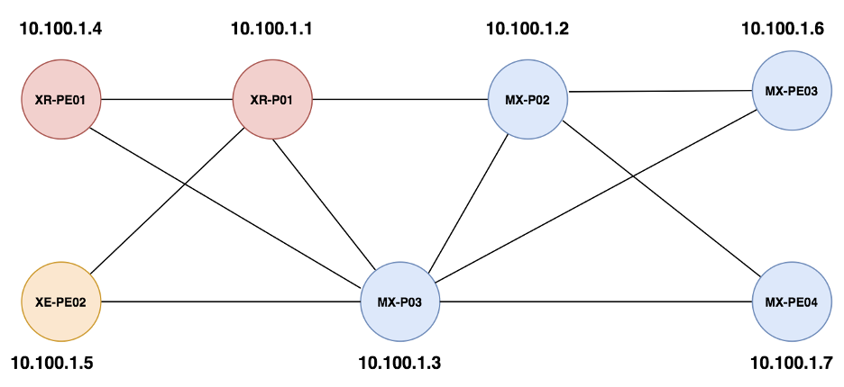
The Network Setup that we will use in this series is shown below:
- It includes Cisco and Juniper virtual routers.
- Below devices forms an MPLS network with (3 Core + 4 Provider Edge routers).
- Segment Routing is used and preferred over LDP.
One of the key properties of SR is that MPLS labels are distributed via the Interior Gateway Protocol (IGP), ISIS or OSPF, rather than a dedicated label distribution protocol. Another benefit is the concept of Source Routing that implies encoding the path a packet traverse by means of a stack of headers applied to the packet when launching it into the network. These headers/labels what we call SID “Segment ID” in the SR world.
Node Segments
Allow us to ask you this question; What is the range of label blocks reserved for SR in Cisco IOS-XR, and Juniper JunOS ?
- IOS-XR –> 16000 till 23900
- JunOS –> By default no reserved block
Node SID is a special type of Prefix-SID. Each node in the network has a node segment associated with its loopback address. (however, it can have multiple prefix segments).
Any other node in the network can send packets to it along the shortest IGP path by using that node segment.
The routers in the network use the following two parameters in order for each node in the network to build the Node segment for each node in the network
- Node index: Each router must have a unique node index. This is also known as a Node-SID
- Label Stack: This is defined in terms of a start-label and a label-range. The label range must be wide enough to accommodate all of the routers in the domain (including anticipated future growth). This label range is known as the segment routing global block (SRGB).
Below is the basic configuration to enable SR on IOS-XR devices and specify the Node-SID using the index
router isis 100
net 49.0000.0000.0001.00
address-family ipv4 unicast
metric-style wide
segment-routing mpls
!
interface Loopback0
passive
address-family ipv4 unicast
prefix-sid index 1
!
!
Below is the basic configuration to enable SR on JunOS devices and specify the Node-SID using the index
isis {
source-packet-routing {
node-segment ipv4-index 402;
}
level 2 wide-metrics-only;
level 1 disable;
}
With the above configuration, we can observe the Node-SID advertised in the ISIS database as shown below
LSPID LSP Seq Num LSP Checksum LSP Holdtime/Rcvd ATT/P/OL
XR-P01.00-00 * 0x00000009 0xfab6 697 /* 0/0/0
Area Address: 49
NLPID: 0xcc
IP Address: 10.100.1.1
Metric: 0 IP-Extended 10.100.1.1/32
Prefix-SID Index: 1, Algorithm:0, R:0 N:1 P:0 E:0 V:0 L:0
Prefix Attribute Flags: X:0 R:0 N:1
Hostname: XR-P01
Router Cap: 10.100.1.1, D:0, S:0
Segment Routing: I:1 V:0, SRGB Base: 16000 Range: 8000
In IOS-XR by default, the OS reserves a label block from 16000 with a range of 8000 to be allocated for SR global block for Node segments.
For Juniper devices, we can see the Node-SID and the SRGB block as shown below
LSPID LSP Seq Num LSP Checksum LSP Holdtime/Rcvd ATT/P/OL
MX-P02.00-00 0x00000026 0xc871 899 /1198 0/0/0
Area Address: 49
Hostname: MX-P02
Router Cap: 10.100.1.2, D:0, S:0
Segment Routing: I:1 V:1, SRGB Base: 12560 Range: 4096
SR Algorithm:
Algorithm: 0
Prefix-SID Index: 402, Algorithm:0, R:0 N:1 P:0 E:0 V:0 L:0
In Juniper by default, there is no default label block allocated for SR and the system computes a block for SR in case an SRGB block is not statically configured.
With the above basic configuration, each router calculates the label to reach a specific node using the following formula:
Node Segment to reach PeerX = SRGB advertised by downstream peer + Node-index advertised for PeerX
Node Segment Calculated for PeerX = SRGB for local router + Node-index advertised for PeerX
So we can see that the following is the MPLS forwarding table for XR-P01 to reach MX-PE01
RP/0/RP0/CPU0:XR-P01#sh mpls forwarding
Local Outgoing Prefix Outgoing Next Hop Bytes
Label Label or ID Interface Switched
------ ----------- ------------------ ------------ --------------- ------------
16004 Pop SR Pfx (idx 4) Gi0/0/0/2 172.20.1.6 2156
16402 Pop SR Pfx (idx 402) Gi0/0/0/0 172.20.1.1 3224
16403 Pop SR Pfx (idx 403) Gi0/0/0/1 172.20.1.3 731
16406 12966 SR Pfx (idx 406) Gi0/0/0/0 172.20.1.1 198
4774 SR Pfx (idx 406) Gi0/0/0/1 172.20.1.3 733
The below diagram outlines the calculation
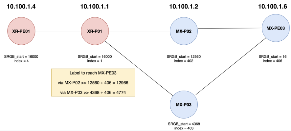
We can see that the label assigned for each node across the network is not consistent and it is very similar to LDP. Thus the recommended approach is to unify the SRGB on all devices in order to have a consistent calculation for the Node Segment across the network
Below is the configuration required on IOS-XR devices
segment-routing
global-block 400000 400999
Below is the configuration required on JunOS devices
isis {
source-packet-routing {
srgb start-label 400000 index-range 1000;
node-segment ipv4-index 403;
}
}
We can verify that the Node-Segment assigned to all the devices is consistent as shown below from XR-P01 output
RP/0/RP0/CPU0:XR-P01#sh mpls forwarding
Local Outgoing Prefix Outgoing Next Hop Bytes
Label Label or ID Interface Switched
------ ----------- ------------------ ------------ --------------- ------------
400402 Pop SR Pfx (idx 402) Gi0/0/0/0 172.20.1.1 474
400403 Pop SR Pfx (idx 403) Gi0/0/0/1 172.20.1.3 474
400406 400406 SR Pfx (idx 406) Gi0/0/0/0 172.20.1.1 0
400406 SR Pfx (idx 406) Gi0/0/0/1 172.20.1.3 297
400407 400407 SR Pfx (idx 407) Gi0/0/0/0 172.20.1.1 217
400407 SR Pfx (idx 407) Gi0/0/0/1 172.20.1.3 0
The below is the output from Juniper MX-PE03 node that outlines the Node-SID
MX-PE03# run show route table inet.3
inet.3: 5 destinations, 5 routes (5 active, 0 holddown, 0 hidden)
+ = Active Route, - = Last Active, * = Both
10.100.1.1/32 *[L-ISIS/14] 00:03:43, metric 2000
to 172.20.1.15 via ge-0/0/0.0, Push 400001
> to 172.20.1.17 via ge-0/0/1.0, Push 400001
10.100.1.2/32 *[L-ISIS/14] 02:13:37, metric 1000
> to 172.20.1.15 via ge-0/0/0.0
10.100.1.3/32 *[L-ISIS/14] 00:52:20, metric 1000
> to 172.20.1.17 via ge-0/0/1.0
10.100.1.4/32 *[L-ISIS/14] 00:27:56, metric 2000
> to 172.20.1.17 via ge-0/0/1.0, Push 400004
10.100.1.7/32 *[L-ISIS/14] 00:11:38, metric 2000
to 172.20.1.15 via ge-0/0/0.0, Push 400407
> to 172.20.1.17 via ge-0/0/1.0, Push 400407
The below diagram outlines the Node-SID in the network
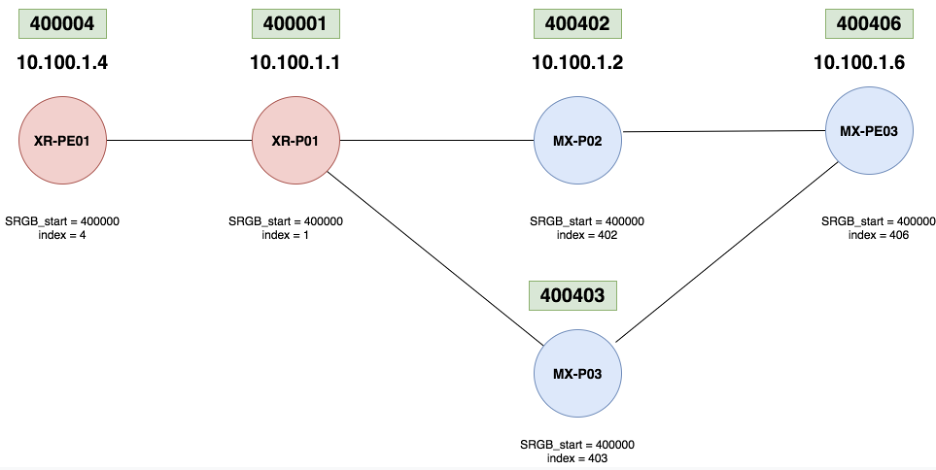
Let’s conclude this article by listing the advantages of Using Node Segments Instead of LDP:
- You have already seen the first advantage – the fact that when configuring the same SRGB on each router, the label required to reach a given router is the same throughout the network, rather than changing hop-by-hop as in the LDP case.
- the second advantage is having fewer protocols to configure and monitor. LDP can be removed from the network.
- The path can be treated as direction instead of hop-by-hop, when you point to 40406 all routers in the middle will freely independently decide how to reach it.


